Overview
ROLE
Product Designer
Metalsmith
TOOLS
Adobe Creative Suite (Ai, Lr, Id)
Machine shop, Laser Cutter, Waterjet
TIME FRAME
6 Weeks
Spring 2020
Project Background
A lamp that celebrates the beauty of light
This project involved exploring how you would design a 6-foot lamp for a specific environment. We were required to use metal as the base structure, but were free to explore various materials to see how light interacts with it. The focus would be on manufacturing and incorporation into environment.
Research
Designing for an Office Space
Going into this, I knew I wanted to use an element that brought forth an explosion of color. I wanted my lamp to function as a decorative element in an office space so I geared more towards modern, playful spaces where I could add some color into an otherwise minimalist setting. The primary purpose of my lamp would not be providing light, but to set the mood as a sculptural piece in the lobby. I also looked into the various ways light interacted with color.
Concept Ideation
Playful, Sharp, Opalescent
I started to develop ideas that used a dichromatic film to add color when light shone through it. I varied between using optical fiber and LED panels. I also decided to experiment with scale, seeing how the lamp would be at a more traditional 6-foot height or as a wall installation. Going forth, I chose to proceed in a more geometric, faceted concept to form a crystalline sculpture.
Concept Development
Crystalline and Faceted
I switched to developing an abstract, crystal form for my lamp, with it transitioning from a closed “rock” shape to translucent facets. I chose to make the form out of triangles and since it was abstracted, I wanted it to come together as I built my prototype and grow it organically. This is what would make it truly “abstract”.
Iridescent like Stained Glass
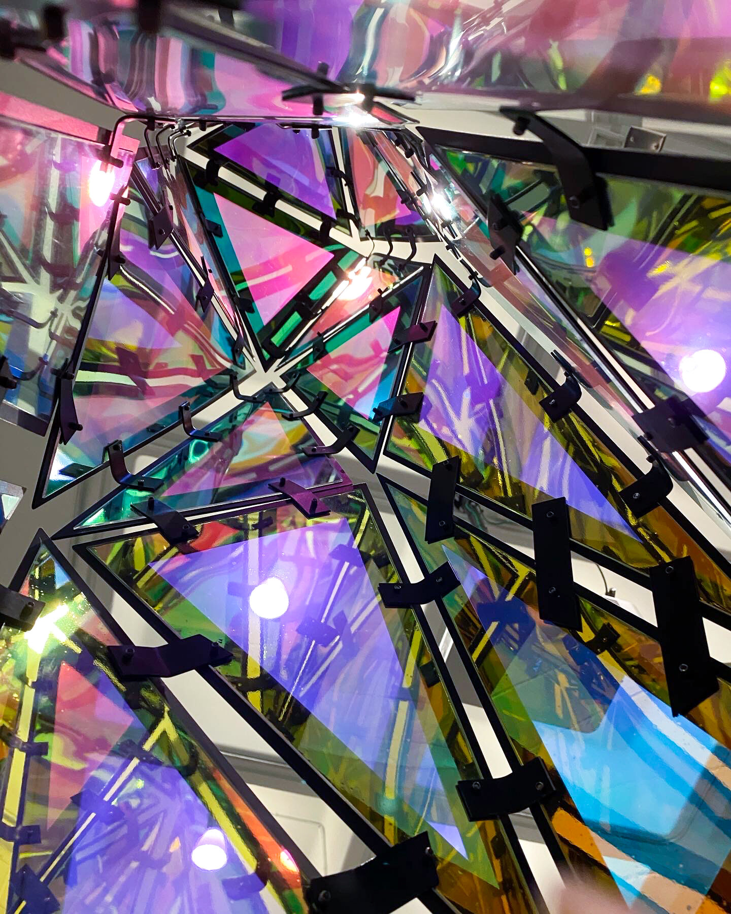
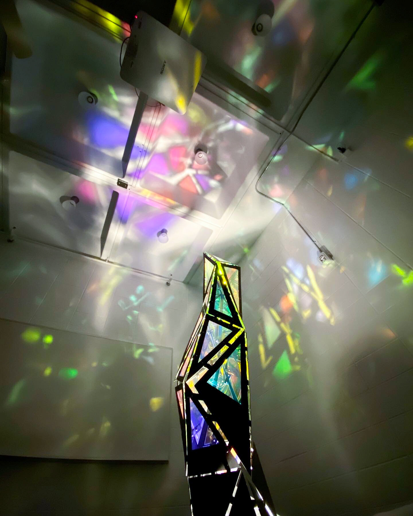
To convey the “crystal” element of my lamp, I chose to use a dichromatic film stuck to acrylic. It would display different colors in accordance to where you see it from when the light is off, and create a stained glass effect on its surroundings when it is turned on.
Prototyping
Lasercutting
I started out by individually measuring and assembling lasercut triangles out of cardboard with little bent cardboard tabs. The triangles were drawn on Adobe Illustrator and I used the Illustrator file as a template to lasercut. This ensured that I would grow a faceted form, and that it remained abstract. I numbered each triangle to know their general placement.
Growing the form
It was a painstaking process to see how slowly the triangles were being built. After constructing the solid triangle base, I transitioned into the open triangles, which indicated where the facets turned into acrylic panels. This finished cardboard prototype would function as a layout model for my final lamp model.
Materials
Aluminum
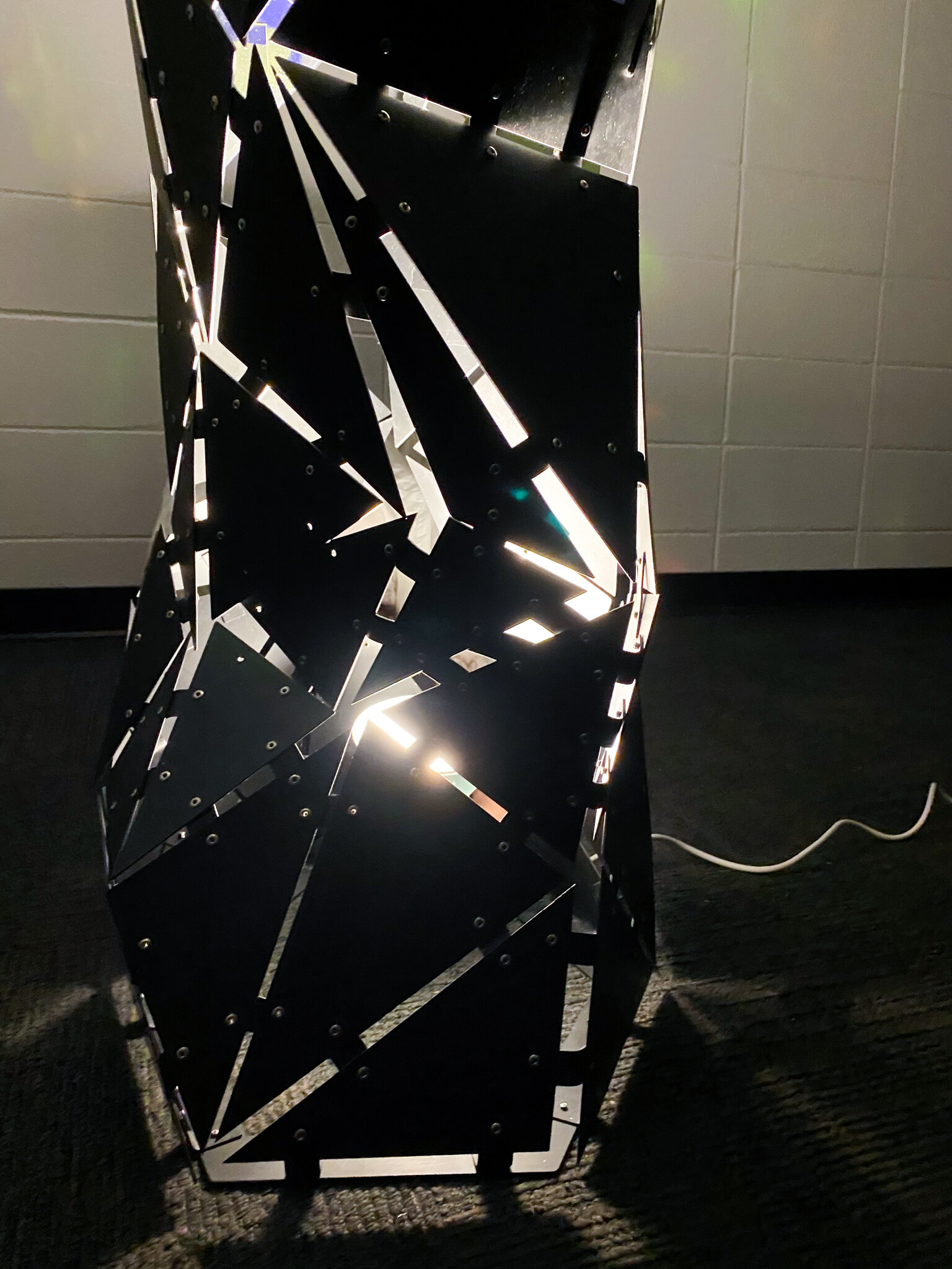
I chose aluminum as it would be a lightweight material for the triangles. I didn’t want the lamp warping from the weight, so I went with 0.162 inch thickness, and spray painted it a matte black. I used steel tabs to connect the aluminum triangles so that they would stay strong and would not warp.
Iridescent Window Film
This film was applied onto 1/8 inch acrylic panels, to be riveted on to the aluminum triangles later on. The acrylic facets would appear transparent from an angle, and shine various colors from another.
Rivets
To attach the triangles, tabs, and acrylic triangles I decided to use rivets. I didn’t want to weld, as I thought it would make the seams messy, and I didn’t want to use bolts since it would make it look too bulky. Rivets were easy to attach, allowed for blind joining, and kept the overall form clean.
Construction
Using a Waterjet
Using the Illustrator files I used for my prototype, I created a waterjet template to cut out the parts for my final model. I used a general hexagon shape when designing the form to group and create the facets. To fit all 65 triangles on the 4’ x 8’ aluminum sheet, I had to play around with the orientation to ensure the least amount of material was wasted. The labelled numbers ensured that the correct triangles are joined together. I also chose to draw the rivet holes in Illustrator so that I wouldn’t have to drill them when assembling later on.
Construction
Preparing
I sanded all the waterjet cut triangles and began labelling them and spray painting them black. The acrylic triangles were lasercut to size, and I applied the window film on them so that they were ready to go.
Attaching
Next, I began setting up the solid triangle base and bending the tabs as I went. I found that attaching the triangles in clusters ensured that I made fewer angle errors when assembling later on.
Assembling
Finally, I used my cardboard prototype as reference to attach the clusters of triangles together with rivets. I corrected any gaping holes by re-bending and re-attaching the triangles.
Finished model
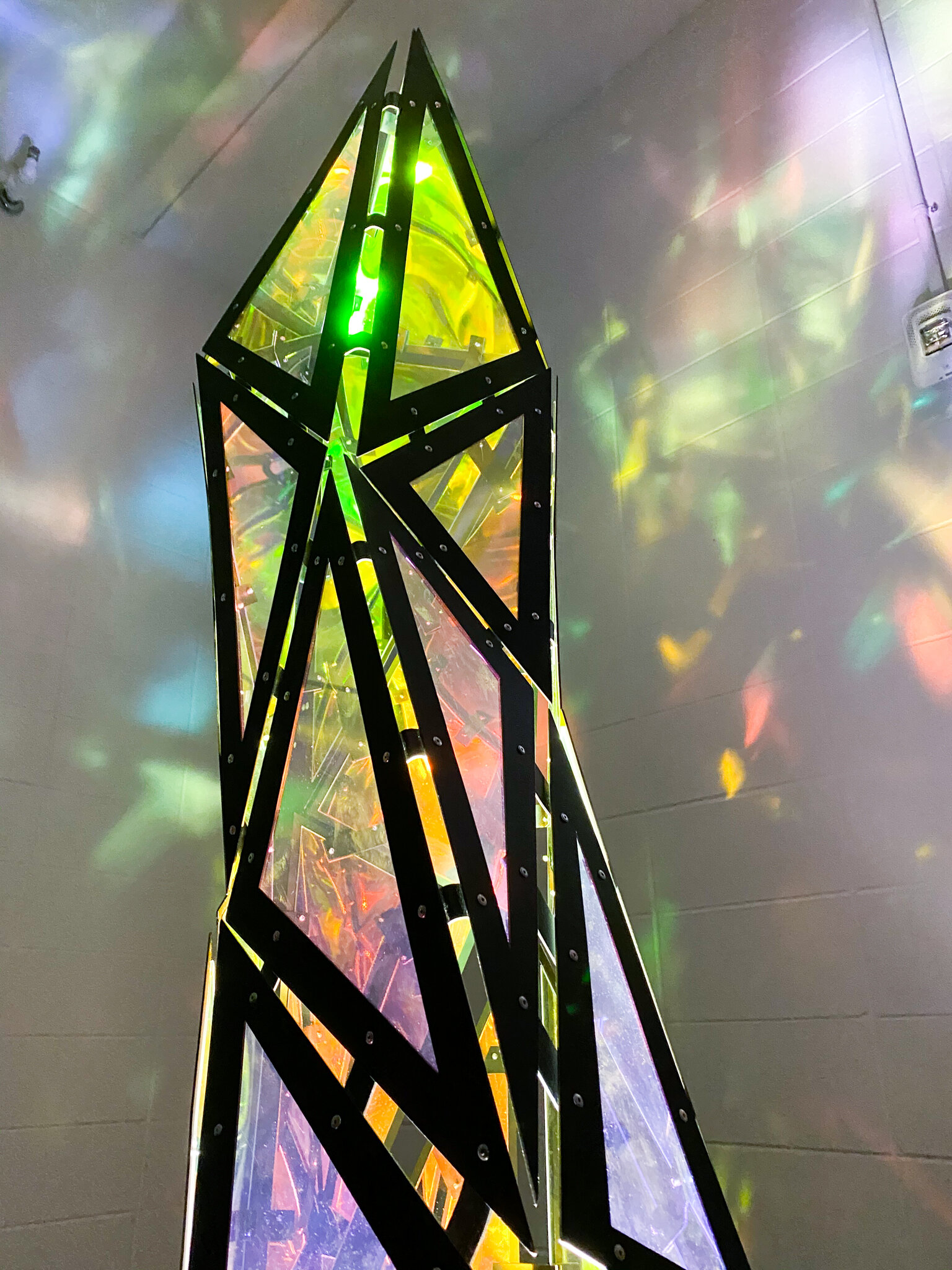
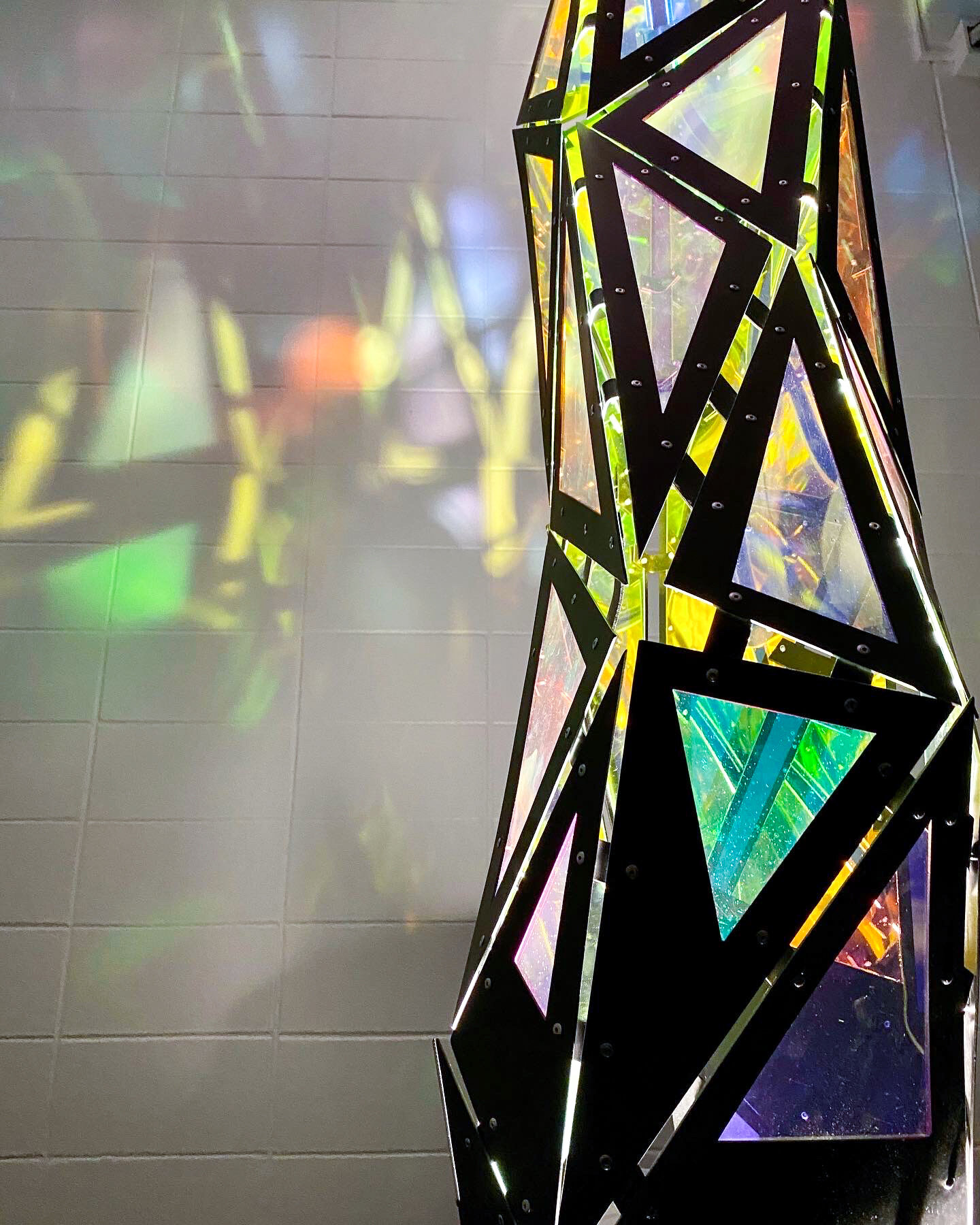
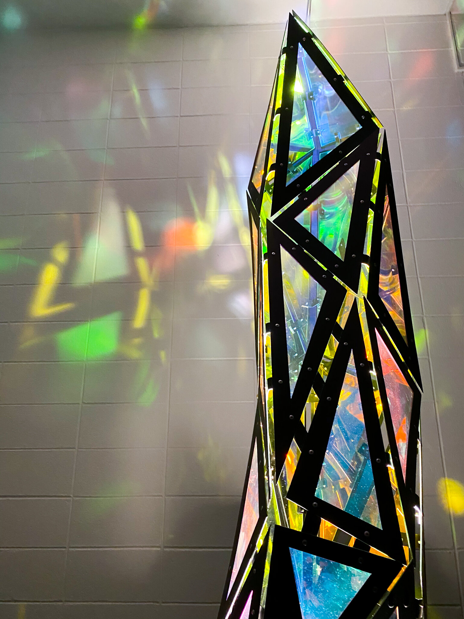
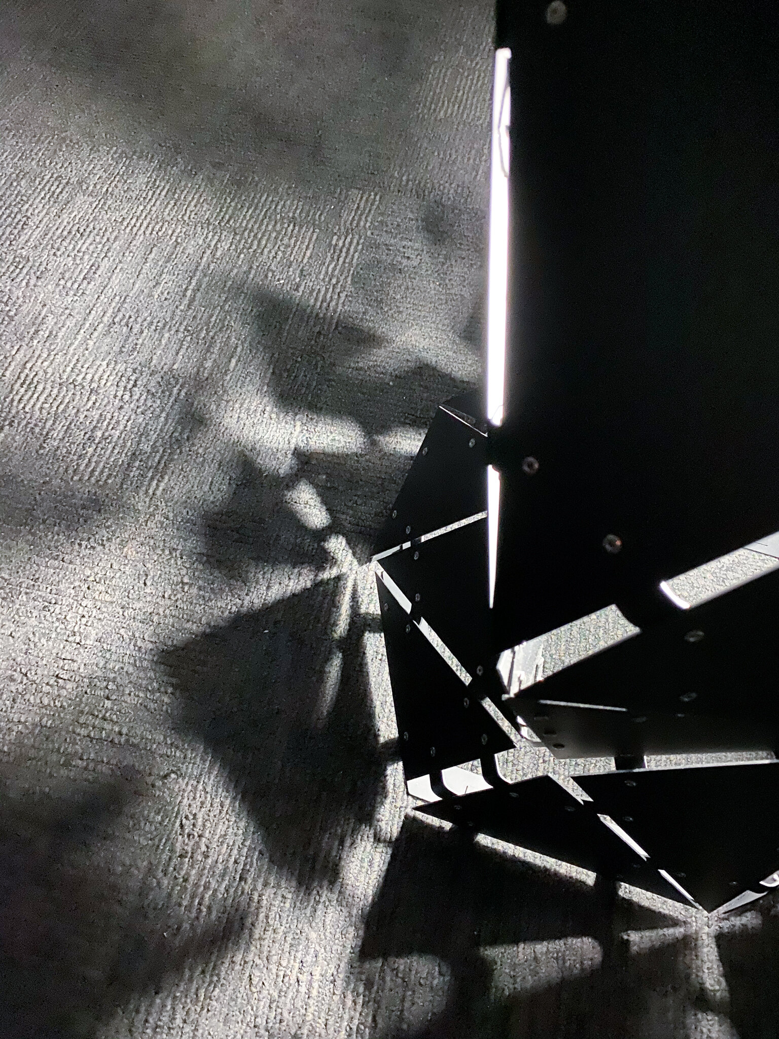
And it’s done! It took days and days of sleepless labor, and I have many of my friends to thank for the assembly. The mosaics created on the wall were far more stunning in person, and I was happy with how it reflected the light.
Reflections
I made many, many manufacturing errors while constructing this project. Since everything had to be labelled, and each tab was uniquely bent and drilled, it took ages to assemble. It was also impossible to construct alone so I needed one or two extra pairs of hands at all times. Frustratingly, almost every step of the process kept going wrong--including painting. Though it sounds obvious, I didn’t consider how rigid metal is when assembled. I thought that everything would “come together” as I joined it together, similar to what happened with my prototype. Obviously, that’s not what happened. A 5 degree difference in the angle on a lower row would turn into a 25 degree change as it grows higher, forcing me to drill through the rivets and start over.
I can now see that by considering how a product will be manufactured at a large scale, and using those methods to downsize it and make my one model, a lot of unnecessary steps and design decisions are reduced. If I were to construct this again, I would cut the triangles out with the tabs attached (so I would just bend them) and definitely reduce the number of parts!


